Submarine communications cable
Template loop detected: Template:Cleanup-restructure
A submarine communications cable is a cable laid beneath the sea to carry telecommunications between countries.
The first submarine communications cables carried telegraphy traffic. Subsequent generations of cables carried first telephony traffic, then data communications traffic. All modern cables use fibre optic technology to carry digital payloads, which are then used to carry telephone traffic as well as Internet and private data traffic.
As of 2005, submarine cables link all the world's continents except Antarctica.
History
Trials
After William Cooke and Charles Wheatstone had introduced their working telegraph in 1839, the idea of a submarine line across the Atlantic Ocean began to be thought of as a possible triumph of the future. Samuel Morse proclaimed his faith in it as early as the year 1840, and in 1842 he submerged a wire, insulated with tarred hemp and India rubber, in the water of New York harbour, and telegraphed through it. The following autumn Wheatstone performed a similar experiment in Swansea bay. A good insulator to cover the wire and prevent the electric current from leaking into the water was necessary for the success of a long submarine line. India rubber had been tried by Moritz von Jacobi, the Russian electrician, as far back as 1811.
Another insulating gum which could be melted by heat and readily applied to wire made its appearance in 1842. Gutta-percha, the adhesive juice of the Palaquium gutta tree, was introduced to Europe by William Montgomerie, a Scottish surgeon in the service of the British East India Company. Twenty years earlier he had seen whips made of it in Singapore, and he believed that it would be useful in the fabrication of surgical apparatus. Michael Faraday and Wheatstone soon discovered the merits of gutta-percha as an insulator, and in 1845 the latter suggested that it should be employed to cover the wire which was proposed to be laid from Dover to Calais. It was tried on a wire laid across the Rhine between Deutz and Cologne. In 1849 C.V. Walker, electrician to the South Eastern Railway, submerged a wire coated with it, or, as it is technically called, a gutta-percha core, along the coast off Dover.
The first commercial cables
In August 1850, John Watkins Brett's Anglo-French Telegraph Company laid the first line across the English Channel. It was simply a copper wire coated with gutta-percha, without any other protection. The experiment served to keep alive the concession, and the next year, on November 13, 1851, a protected core, or true cable, was laid from a government hulk, the Blazer, which was towed across the Channel. The next year, Great Britain and Ireland were linked together. In 1852, a cable laid by the Submarine Telegraph Company linked London to Paris for the first time. In May, 1853, England was joined to the Netherlands by a cable across the North Sea, from Orford Ness to The Hague. It was laid by the Monarch, a paddle steamer which had been fitted for the work.
Transatlantic telegraph cable
The first transatlantic telegraph cable was promoted by Cyrus Field and laid in 1858. However, the project was plagued with problems from the outset, and was in operation for only a month. Subsequent attempts in 1865 and 1866 were more successful.
Submarine cable to India, Singapore, the Far East and Australasia
An 1863 cable to Bombay provided a crucial link to the Saudi peninsula. In 1870 Bombay was linked to London via submarine cable in a combined operation by four cable companies, at the behest of the British Government. In 1872 these four companies were combined to form the mammoth globespanning Eastern Telegraph Company, owned by John Pender. A spin-off from Eastern Telegraph Company was a second sister company, the Eastern Extension, China and Australasia Telegraph Company, commonly known simply as "the Extension".
Submarine cable across the Pacific
This was completed in 1902–03, linking the US mainland to Hawaii in 1902 and Guam to the Philippines in 1903.[1] Canada, Australia, New Zealand and Fiji were also linked in 1902. [2]
Construction
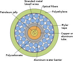
Transatlantic cables of the 19th century consisted of an outer layer of iron and later steel wire, wrapping India rubber, wrapping gutta-percha, which surrounded a multi-stranded copper wire at the core. The portions closest to each shore landing had additional protective armor wires. Gutta-percha, a natural polymer similar to rubber, had nearly ideal properties for insulating submarine cables, aside from a rather high dielectric constant which made cable capacitance high. Gutta-percha was not replaced as a cable insulation until polyethylene was introduced in the 1930s. Gutta-percha was so critical to communications that in the 1920s the American military experimented with rubber-insulated cables, since American interests controlled significant supplies of rubber but no gutta-percha manufacturers.
Bandwidth problems
Early long-distance submarine telegraph cables exhibited formidable electrical problems. Unlike modern cables, the technology of the 19th century did not allow for in-line repeater amplifiers in the cable. Large voltages were used to attempt to overcome the electrical resistance of their tremendous length but the cables' distributed capacitive and inductive reactance combined to attenuate the telegraph pulses in the line, severely limiting the data rate for telegraph operation. In modern terms, the cables had very limited bandwidth.
As early as 1823, Francis Ronalds had observed that electric signals were retarded in passing through an insulated wire or core laid underground, and the same effect was noticeable on cores immersed in water, and particularly on the lengthy cable between England and The Hague. Michael Faraday showed that the effect was caused by capacitance between the wire and the earth (or water) surrounding it. Faraday had noted that when a wire is charged from a battery (for example when pressing a telegraph key), the electric charge in the wire induces an opposite charge in the water as it travels along. As the two charges attract each other, the exciting charge is retarded. The core acts as a capacitor distributed along the length of the cable which, coupled with the resistance and inductance of the cable limits the speed at which a signal travels through the conductor of the cable.
Early cable designs failed to analyze these effects correctly. Famously, E.O.W. Whitehouse had dismissed the problems and insisted that a transatlantic cable was feasible. When he subsequently became electrician of the Atlantic Telegraph Company he became involved in a public dispute with William Thomson. Whitehouse believed that, with enough voltage, any cable could be driven. Because of the excessive voltages recommended by Whitehouse, Cyrus Field's first transatlantic cable never worked reliably, and eventually short circuited to the ocean when Whitehouse increased the voltage beyond the cable design limit.
Thomson designed a complex electric-field generator that minimized current by resonating the cable, and a sensitive light-beam mirror galvanometer for detecting the faint telegraph signals. Thomson became wealthy on the royalties of these, and several related, inventions. Thomson was elevated to Lord Kelvin for his contributions in this area, chiefly an accurate mathematical model of the cable, which permitted design of the equipment for accurate telegraphy. The effects of atmospheric electricity and the geomagnetic field on submarine cables also motivated many of the early polar expeditions.
Thomson had produced a mathematical analysis of propagation of electrical signals into telegraph cables based on their capacitance and resistance, but since long submarine cables operated at slow rates, he did not include the effects of inductance. By the 1890s, Oliver Heaviside had produced the modern general form of the telegrapher's equations which included the effects of inductance and which were essential to extending the theory of transmission lines to higher frequencies required for high-speed data and voice.
Transatlantic telephony
While laying a transatlantic telephone cable was seriously considered from the 1920s, a number of technological advances were required for cost-efficient telecommunications that did not arrive until the 1940s.
In 1942, Siemens Brothers, in conjunction with the United Kingdom National Physical Laboratory, adapted submarine communications cable technology to create the world's first submarine oil pipeline in Operation Pluto during World War II.
TAT-1 (Transatlantic No. 1) was the first transatlantic telephone cable system. Between 1955 and 1956, cable was laid between Gallanach Bay, near Oban, Scotland and Clarenville, Newfoundland and Labrador. It was inaugurated on September 25, 1956, initially carrying 36 telephone channels.
Technological developments
In the 1960s, transoceanic cables were waveguides transmitting frequency-multiplexed radio signals. The repeaters were the most reliable vacuum tube amplifiers ever designed. A high voltage direct current wire powered the repeaters. Many of these cables still exist and are usable, but abandoned because their capacity is too small to be commercially viable. Some have been used as scientific instruments to measure earthquake waves and other geomagnetic events.
In the 1980s, fibre optic cables were developed. The first transatlantic telephone cable to use optical fibre was TAT-8, which went into operation in 1988.
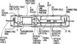
Modern optical fibre repeaters use a solid-state optical amplifier, usually an Erbium-doped fibre amplifier. Each repeater contains separate equipment for each fibre. These comprise signal reforming, error measurement and controls. A solid-state laser despatches the signal into the next length of fibre. The solid-state laser excites a short length of doped fibre that itself acts as a laser amplifier. As the light passes through the fibre, it is amplified. This system also permits wavelength-division multiplexing, which dramatically increases the capacity of the fibre.
Repeaters are powered by a constant direct current passed down the conductor near the centre of the cable, so all repeaters in a cable are in series. Power feed equipment is installed at the terminal stations, The power feed current is returned through what is called a sea earth.
The optic fibre used in undersea cables is chosen for its exceptional clarity, permitting runs of more than 100 kilometres between repeaters to minimize the number of amplifiers and the distortion they cause.
Originally, submarine cables were simple point-to-point connections. With the development of submarine branching units (SBUs), more than one destination could be served by a single cable system. Modern cable systems now usually have their fibres arranged in a self-healing ring to increase their redundancy, with the submarine sections following different paths on the ocean floor. One driver for this development was that the capacity of cable systems had become so large that it was not possible to completely back-up a cable system with satellite capacity, so it became necessary to provide sufficient terrestrial back-up capability. Not all telecommunications organizations wish to take advantage of this capability, so modern cable systems may have dual landing points in some countries (where back-up capability is required) and only single landing points in other countries where back-up capability is either not required, the capacity to the country is small enough to be backed up by other means, or having back-up is regarded as too expensive.
A further redundant-path development over and above the self-healing rings approach is the "Mesh Network" whereby fast switching equipment is used to transfer services between network paths with little to no effect on higher-level protocols if a path becomes inoperable. As more paths become available to use between two points, the less likely it is that one or two simultaneous failures will prevent end-to-end service.
Cable repair
Cables can be broken by fishing trawlers, anchoring, undersea avalanches and even shark bites. Breaks were common in the early cable laying era due to the use of simple materials and the laying of cables directly on the the ocean floor rather than burying the cables in trenches in vulnerable areas. Cables were also sometimes cut by enemy forces in wartime. The Newfoundland earthquake of 1929 broke a series of trans-Atlantic cables by triggering a massive undersea avalanche. The sequence of breaks helped scientists chart the progress of the avalanche. The 2006 Hengchun earthquake on December 26, 2006 rendered numerous cables near Taiwan inoperable.
To effect repairs on deep cables, the damaged portion is brought to the surface using a grapple. Deep cables must be cut at the seabed and each end separately brought to the surface, whereupon a new section is spliced in. The repaired cable is longer than the original, so the excess is deliberately laid in a 'U' shape on the sea-bed. A submersible can be used to repair cables that are near the surface.
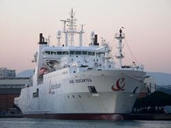
A number of ports near important cable routes became homes to specialised cable repair ships. Halifax, Nova Scotia was home to a half dozen such vessels for most of the 20th century including long-lived vessels such as the CS Cyrus Field, CS Minia and CS Mackay-Bennett. The latter two were contracted to recover victims from the sinking of the RMS Titanic. The crews of these vessels developed many new techniques to repair and improve cable laying, such as the "plough", a device to bury cables.
Owners and operators of cable-laying ships
- TYCO[1]
- ASN Marine[2]
- Elettra;
- FT Marine[3]
- Global Marine Systems Limited[4]
- NTT World Engineering Marine Corporation (NTT-WEM)[5]
- S. B. Submarine Systems[6]
- YIT Primatel Ltd.
- E-MARINE[7]
- IT International Telecom Inc.[8]
- Subsea 7.[9]
See also
- List of international submarine communications cables
- Communications satellite
- Internet
- Transatlantic telegraph cable
- Transatlantic telephone cable
- Optical fibre
- Public switched telephone network
ReferencesISBN links support NWE through referral fees
- ↑ Tyco Telecommunications - Marine Services. Retrieved November 14, 2005.
- ↑ http://www.offshore-technology.com/contractors/cables/teledenmark/. Retrieved November 14, 2005.
- ↑ http://www.marine.francetelecom.com/en/. Retrieved February 5, 2006.
- ↑ Global Marine Systems Limited. Retrieved November 14, 2005.
- ↑ NTT World Engineering Marine Corporation (NTT-WEM). Retrieved November 14, 2005.
- ↑ S. B. Submarine Systems. Retrieved November 14, 2005.
- ↑ Emirates Telecommunications & marine Services FZE. Retrieved May 31, 2006.
- ↑ IT International Telecom Inc.. Retrieved June 13, 2006.
- ↑ Subsea 7.. Retrieved May 16, 2007.
External links
- Submarine Cable Market Overview, December, 2006 — includes details of many major submarine cable systems
- Global Communications Submarine Cable Map, 2007
- Alcatel Optical Fiber Submarine systems Map, 2005.
- Analysis of the submarine cable industry. Registration required.
- Timeline of Submarine Communications Cables, 1850-2006
- History of the Atlantic Cable & Submarine Telegraphy - Wire Rope and the Submarine Cable Industry
- The International Cable Protection Committee — includes a register of submarine cables worldwide (though not always updated as often as one might hope)
- The UK Cable Protection Committee
- Kingfisher Information Service — source of free maps of cable routes around the UK
- France Telecom's Fishermen's/Submarine Cable Information
- Oregon Fisherman's Cable Committee
- Cableships of the World
- A short history of telegraphy
- An Oversimplified Overview of Undersea Cable Systems
- SAT3 WASC SAFE Undersea Cable
- Comprehensive list of the approximately 1000 cable landing sites globally
- List of the suppliers of the world's undersea communications cables
- Internet/Tel Undersea Cables of the World
- Map of all submarine communications cables currently in use, KDDI, July 2002
- Map and Satellite views of US landing sites for transatlantic cables
- Map and Satellite views of US landing sites for transpacific cables
- 1939 Article on Laying Submarine Cables
- Mother Earth Mother Board - Wired article by Neal Stephenson about submarine cables
- Maps of communications cable routes. Retrieved February 12, 2006.
- Submarine Telecommunications Newsletter. Retrieved February 12, 2006.
- Submarine Cables in 2006. Retrieved December 11, 2006.
- Earthquakes Disrupt Internet Access in Asia; A Series of Powerful Earthquakes Damages Undersea Cables and Interrupts Internet Connections in Asia. Retrieved December 27, 2006.
- Nature article - Geomagnetic induction on a transatlantic communications cable
- Hunt, Bruce J. Lord Cable. Europhysics News (2004), Vol. 35 No 6.
cs:Podmořský kabel de:Seekabel es:Cable submarino fr:Câble sous-marin id:Kabel komunikasi bawah laut it:Cavo sottomarino he:כבל תת ימי ja:海底ケーブル fi:Merikaapeli nl:Onderzeekabel sv:Atlantkabeln zh:海底電纜


