Computer graphics
Computer graphics, a subfield of computer science, is concerned with digitally synthesizing and manipulating visual content. Although the term often refers to three-dimensional (3D) computer graphics, it also encompasses two-dimensional (2D) graphics and image processing. Graphics is often differentiated from the field of visualization, although the two have many similarities. Entertainment (in the form of animated movies and video games) is perhaps the most well-known application of computer graphics.
Today, computer graphics can be seen in almost every illustration made. Computer graphics are often used by photographers to improve photos. It also has many other applications, ranging from the motion picture industry to architectural rendering. As a tool, computer graphics, which were once very expensive and complicated, can now be used by anyone in the form of freeware. In the future, computer graphics could possibly replace traditional drawing or painting for illustrations. Already, it is being used as a form of enhancement for different illustrations.
Branches
Some major subproblems in computer graphics include:
- Describing the shape of an object (modeling)
- Describing the motion of an object (animation)
- Creating an image of an object (rendering)
Modeling
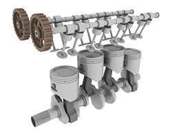
Modeling describes the shape of an object. The two most common sources of 3D models are those created by an artist using some kind of 3D modeling tool, and those scanned into a computer from real-world objects. Models can also be produced procedurally or via physical simulation.
Because the appearance of an object depends largely on the exterior of the object, boundary representations are most common in computer graphics. Two dimensional surfaces are a good analogy for the objects used in graphics, though quite often these objects are non-manifold. Since surfaces are not finite, a discrete digital approximation is required: Polygonal meshes (and to a lesser extent subdivision surfaces) are by far the most common representation, although point-based representations have been gaining some popularity in recent years. Level sets are a useful representation for deforming surfaces which undergo many topological changes such as fluids.
Subfields
- Subdivision surfaces—A method of representing a smooth surface via the specification of a coarser piecewise linear polygon mesh.
- Digital geometry processing—surface reconstruction, mesh simplification, mesh repair, parameterization, remeshing, mesh generation, mesh compression, and mesh editing all fall under this heading.
- Discrete differential geometry—DDG is a recent topic which defines geometric quantities for the discrete surfaces used in computer graphics.
- Point-based graphics—a recent field which focuses on points as the fundamental representation of surfaces.
Shading
Texturing, or more generally, shading, is the process of describing surface appearance. This description can be as simple as the specification of a color in some colorspace or as elaborate as a shader program which describes numerous appearance attributes across the surface. The term is often used to mean "texture mapping," which maps a raster image to a surface to give it detail. A more generic description of surface appearance is given by the bidirectional scattering distribution function, which describes the relationship between incoming and outgoing illumination at a given point.
Animation
Animation refers to the temporal description of an object, that is, how it moves and deforms over time. There are numerous ways to describe these motion, many of which are used in conjunction with each other. Popular methods include keyframing, inverse kinematics, and motion capture. As with modeling, physical simulation is another way of specifying motion.
Rendering
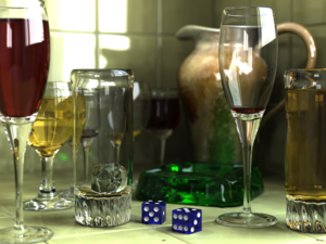
Rendering converts a model into an image either by simulating light transport to get physically-based photo-realistic images, or by applying some kind of style as in non photo-realistic rendering.
Subfields
- Physically-based rendering—concerned with generating images according to the laws of geometric optics
- Real time rendering—focuses on rendering for interactive applications, typically using specialized hardware like GPUs
- Non-photorealistic rendering
- Relighting—recent area concerned with quickly re-rendering scenes
History
William Fetter was credited with coining the term "Computer Graphics" in 1960, to describe his work at Boeing. One of the first displays of computer animation was in the film Futureworld (1976), which included an animation of a human face and hand—produced by Ed Catmull and Fred Parke at the University of Utah.
The most significant results in computer graphics are published annually in a special edition of the ACM (Association for Computing Machinery) Transactions on Graphics and presented at SIGGRAPH (Special Interest Group for Computer GRAPHics).
History of the Utah teapot
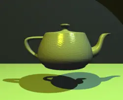
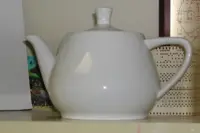
The Utah teapot or Newell teapot is a 3D model that has become a standard reference object (and something of an in-joke) in the computer graphics community. The model was created in 1975, by early computer graphics researcher Martin Newell, a member of the pioneering graphics program at the University of Utah.
Newell needed a moderately simple mathematical model of a familiar object for his work. At the suggestion of his wife Sandra, he sketched their entire tea service by eye. Then he went back to the lab and edited Bezier control points on a Tektronix storage tube, again by hand. While a cup, saucer, and teaspoon were digitized along with the famous teapot, only the teapot itself attained widespread usage.
The teapot shape contains a number of elements that made it ideal for the graphics experiments of the time. Newell made the mathematical data that described the teapot's geometry publicly available, and soon other researchers began to use the same data for their computer graphics experiments. They needed something with roughly the same characteristics that Newell had, and using the teapot data meant they did not have to laboriously enter geometric data for some other object. Although technical progress has meant that the act of rendering the teapot is no longer the challenge it was in 1975, the teapot continued to be used as a reference object for increasingly advanced graphics techniques. Over the following decades, editions of computer graphics journals regularly featured versions of the teapot: Faceted or smooth-shaded, wireframe, bumpy, translucent, refractive, even leopard-skin and furry teapots were created.
2D computer graphics
2D computer graphics is the computer-based generation of digital images—mostly from two-dimensional models (such as 2D geometric models, text, and digital images) and by techniques specific to them. The term may stand for the branch of computer science that comprises such techniques, or for the models themselves.
2D computer graphics are mainly used in applications that were originally developed upon traditional printing and drawing technologies, such as typography, cartography, technical drawing, advertising, and so on. In those applications, the two-dimensional image is not just a representation of a real-world object, but an independent artifact with added semantic value; two-dimensional models are therefore preferred, because they give more direct control of the image than 3D computer graphics (whose approach is more akin to photography than to typography).
In many domains, such as desktop publishing, engineering, and business, a description of a document based on 2D computer graphics techniques can be much smaller than the corresponding digital image—often by a factor of 1/1000 or more. This representation is also more flexible, since it can be rendered at different resolutions to suit different output devices. For these reasons, documents and illustrations are often stored or transmitted as 2D graphic files.
2D computer graphics started in the 1950s, based on vector graphics devices. These were largely supplanted by raster-based devices in the following decades. The PostScript language and the X Window System protocol were landmark developments in the field.
2D graphics techniques
2D graphics models may combine geometric models (also called vector graphics), digital images (also called raster graphics), text to be typeset (defined by content, font style and size, color, position, and orientation), mathematical functions and equations, and more. These components can be modified and manipulated by two-dimensional geometric transformations such as translation, rotation, and scaling.
In object oriented graphics, the image is described indirectly by an object endowed with a self-rendering method—a procedure which assigns colors to the image pixels by an arbitrary algorithm. Complex models can be built by combining simpler objects, in the paradigms of object-oriented programming.
Direct painting
A convenient way to create a complex image is to start with a blank "canvas" raster map (an array of pixels, also known as a bitmap) filled with some uniform background color and then "draw," "paint," or "paste" simple patches of color onto it, in an appropriate order. In particular, the canvas may be the frame buffer for a computer display.
Some programs will set the pixel colors directly, but most will rely on some 2D graphics library and/or the machine's graphics card, which usually implement the following operations:
- Paste a given image at a specified offset onto the canvas
- Write a string of characters with a specified font, at a given position and angle
- Paint a simple geometric shape, such as a triangle defined by three corners or a circle with given center and radius
- Draw a line segment, arc of circle, or simple curve with a virtual pen of given width.
Extended color models
Text, shapes and lines are rendered with a client-specified color. Many libraries and cards provide color gradients, which are handy for the generation of smoothly-varying backgrounds, shadow effects, and so on. The pixel colors can also be taken from a texture, for example, a digital image (thus emulating rub-on screentones and the fabled "checker paint" which used to be available only in cartoons).
Painting a pixel with a given color usually replaces its previous color. However, many systems support painting with transparent and translucent colors, which only modify the previous pixel values. The two colors may also be combined in fancier ways, for example, by computing their bitwise exclusive or. This technique is known as inverting color or color inversion, and is often used in graphical user interfaces for highlighting, rubber-band drawing, and other volatile painting—since re-painting the same shapes with the same color will restore the original pixel values.
Layers
The models used in 2D computer graphics usually do not provide for three-dimensional shapes, or three-dimensional optical phenomena such as lighting, shadows, reflection, refraction, and so on. However, they usually can model multiple layers (conceptually of ink, paper, or film; opaque, translucent, or transparent—stacked in a specific order. The ordering is usually defined by a single number (the layer's depth, or distance from the viewer).
Layered models are sometimes called 2 1/2-D computer graphics. They make it possible to mimic traditional drafting and printing techniques based on film and paper, such as cutting and pasting; and allow the user to edit any layer without affecting the others. For these reasons, they are used in most graphics editors. Layered models also allow better anti-aliasing of complex drawings and provide a sound model for certain techniques such as mitered joints and the even-odd rule.
Layered models are also used to allow the user to suppress unwanted information when viewing or printing a document, for example, roads and/or railways from a map, certain process layers from an integrated circuit diagram, or hand annotations from a business letter.
In a layer-based model, the target image is produced by "painting" or "pasting" each layer, in order of decreasing depth, on the virtual canvas. Conceptually, each layer is first rendered on its own, yielding a digital image with the desired resolution which is then painted over the canvas, pixel by pixel. Fully transparent parts of a layer need not be rendered, of course. The rendering and painting may be done in parallel, that is, each layer pixel may be painted on the canvas as soon as it is produced by the rendering procedure.
Layers that consist of complex geometric objects (such as text or polylines) may be broken down into simpler elements (characters or line segments, respectively), which are then painted as separate layers, in some order. However, this solution may create undesirable aliasing artifacts wherever two elements overlap the same pixel.
2D graphics hardware
Modern computer graphics card displays almost overwhelmingly use raster techniques, dividing the screen into a rectangular grid of pixels, due to the relatively low cost of raster-based video hardware as compared with vector graphic hardware. Most graphic hardware has internal support for blitting operations and sprite drawing. A co-processor dedicated to blitting is known as a Blitter chip.
Classic 2D graphics chips of the late 1970s and early 80s, used in the 8-bit video game consoles and home computers, include:
- Atari's ANTIC (actually a 2D GPU), TIA, CTIA, and GTIA
- Commodore/MOS Technology's VIC and VIC-II
2D graphics software
Many graphical user interfaces (GUIs), including Mac OS, Microsoft Windows, or the X Window System, are primarily based on 2D graphical concepts. Such software provides a visual environment for interacting with the computer, and commonly includes some form of window manager to aid the user in conceptually distinguishing between different applications. The user interface within individual software applications is typically 2D in nature as well, due in part to the fact that most common input devices, such as the mouse, are constrained to two dimensions of movement.
2D graphics are very important in the control peripherals such as printers, plotters, sheet cutting machines, and so on. They were also used in most early video and computer games; and are still used for card and board games such as solitaire, chess, and mahjongg, among others.
2D graphics editors or drawing programs are application-level software for the creation of images, diagrams, and illustrations by direct manipulation (through the mouse, graphics tablet, or similar device) of 2D computer graphics primitives. These editors generally provide geometric primitives as well as digital images; and some even support procedural models. The illustration is usually represented internally as a layered model, often with a hierarchical structure to make editing more convenient. These editors generally output graphics files where the layers and primitives are separately preserved in their original form. MacDraw, introduced in 1984 with the Macintosh line of computers, was an early example of this class; recent examples are the commercial products Adobe Illustrator and CorelDRAW, and the free editors such as xfig or Inkscape. There are also many 2D graphics editors specialized for certain types of drawings such as electrical, electronic and VLSI diagrams, topographic maps, computer fonts, and so forth.
Image editors are specialized for the manipulation of digital images, mainly by means of free-hand drawing/painting and signal processing operations. They typically use a direct-painting paradigm, where the user controls virtual pens, brushes, and other free-hand artistic instruments to apply paint to a virtual canvas. Some image editors support a multiple-layer model; however, in order to support signal-processing operations, like blurring each layer is normally represented as a digital image. Therefore, any geometric primitives that are provided by the editor are immediately converted to pixels and painted onto the canvas. The name raster graphics editor is sometimes used to contrast this approach to that of general editors which also handle vector graphics. One of the first popular image editors was Apple's MacPaint, companion to MacDraw. Modern examples are the free GIMP editor, and the commercial products Photoshop and Paint Shop Pro. This class, too, includes many specialized editors—for medicine, remote sensing, digital photography, and others.
3D computer graphics
3D computer graphics are works of graphic art created with the aid of digital computers and 3D software. The term may also refer to the process of creating such graphics, or the field of study of 3D computer graphic techniques and related technology.
3D computer graphics are different from 2D computer graphics in that a three-dimensional representation of geometric data is stored in the computer for the purposes of performing calculations and rendering 2D images. Such images may be for later display or for real-time viewing.
3D modeling is the process of preparing geometric data for 3D computer graphics, and is akin to sculpting or photography, whereas the art of 2D graphics is analogous to painting. Despite these differences, 3D computer graphics rely on many of the same algorithms as 2D computer graphics.
In computer graphics software, the distinction between 2D and 3D is occasionally blurred; 2D applications may use 3D techniques to achieve effects such as lighting, and primarily 3D may use 2D techniques.
Technology
OpenGL and Direct3D are two popular APIs for generation of real-time imagery. Real-time means that image generation occurs in "real time," or "on the fly," and may be highly user-interactive. Many modern graphics cards provide some degree of hardware acceleration based on these APIs, frequently enabling display of complex 3D graphics in real-time.
Creation of 3D computer graphics
The process of creating 3D computer graphics can be sequentially divided into three basic phases:
- Content creation (3D modeling, texturing, animation)
- Scene layout setup
- Rendering
Modeling
The modeling stage could be described as shaping individual objects that are later used in the scene. There exist a number of modeling techniques, including, but not limited to the following:
<<Please explain briefly what each of the following terms means. (Check the links in Wikipedia.)>>
- Constructive solid geometry
- NURBS modeling
- Polygonal modeling
- Subdivision surfaces
- Implicit surfaces
Modeling processes may also include editing object surface or material properties (for example, color, luminosity, diffuse, and specular shading components—more commonly called roughness and shininess, reflection characteristics, transparency, or opacity, or index of refraction), adding textures, bump-maps and other features.
Modeling may also include various activities related to preparing a 3D model for animation (although in a complex character model this will become a stage of its own, known as rigging). Objects may be fitted with a skeleton, a central framework of an object with the capability of affecting the shape or movements of that object. This aids in the process of animation, in that the movement of the skeleton will automatically affect the corresponding portions of the model. At the rigging stage, the model can also be given specific controls to make animation easier and more intuitive, such as facial expression controls and mouth shapes (phonemes) for lip syncing.
Modeling can be performed by means of a dedicated program (for example, Lightwave Modeler, Rhinoceros 3D, Moray), an application component (Shaper, Lofter in 3D Studio), or some scene description language (as in POV-Ray). In some cases, there is no strict distinction between these phases; in such cases modeling is just part of the scene creation process (this is the case, for example, with Caligari trueSpace and Realsoft 3D).
Particle system are a mass of 3D coordinates which have either points, polygons, splats, or sprites assign to them. They act as a volume to represent a shape.
Process
Scene layout setup
Scene setup involves arranging virtual objects, lights, cameras, and other entities on a scene which will later be used to produce a still image or an animation. If used for animation, this phase usually makes use of a technique called "keyframing," which facilitates creation of complicated movement in the scene. With the aid of keyframing, instead of having to fix an object's position, rotation, or scaling for each frame in an animation, one needs only to set up some key frames between which states in every frame are interpolated.
Lighting is an important aspect of scene setup. As is the case in real-world scene arrangement, lighting is a significant contributing factor to the resulting aesthetic and visual quality of the finished work. As such, it can be a difficult art to master. Lighting effects can contribute greatly to the mood and emotional response effected by a scene, a fact which is well-known to photographers and theatrical lighting technicians.
Tessellation and meshes
The process of transforming representations of objects, such as the middle point coordinate of a sphere and a point on its circumference into a polygon representation of a sphere, is called tessellation. This step is used in polygon-based rendering, where objects are broken down from abstract representations ("primitives") such as spheres, cones, and other shapes, to so-called meshes, which are nets of interconnected triangles.
Meshes of triangles (instead of, for example, squares) are popular as they have proven to be easy to render using scanline rendering.
Polygon representations are not used in all rendering techniques, and in these cases the tessellation step is not included in the transition from abstract representation to rendered scene.
Rendering
Rendering is the final process of creating the actual 2D image or animation from the prepared scene. This can be compared to taking a photo or filming the scene after the setup is finished in real life.
Rendering for interactive media, such as games and simulations, is calculated and displayed in real time, at rates of approximately 20 to 120 frames per second. Animations for non-interactive media, such as feature films and video, are rendered much more slowly. Non-real time rendering enables the leveraging of limited processing power in order to obtain higher image quality. Rendering times for individual frames may vary from a few seconds to several days for complex scenes. Rendered frames are stored on a hard disk then can be transferred to other media such as motion picture film or optical disk. These frames are then displayed sequentially at high frame rates, typically 24, 25, or 30 frames per second, to achieve the illusion of movement.
Several different, and often specialized, rendering methods have been developed. These range from the distinctly non-realistic wireframe rendering through polygon-based rendering, to more advanced techniques such as: Scanline rendering, ray tracing, or radiosity. In general, different methods are better suited for either photo-realistic rendering, or real-time rendering.
In real-time rendering, the goal is to show as much information as possible as the eye can process in a 30th of a second (or one frame, in the case of 30 frame-per-second animation). The goal here is primarily speed and not photo-realism. In fact, here exploitations are made in the way the eye "perceives" the world, and thus, the final image presented is not necessarily that of the real-world, but one which the eye can closely associate to. This is the basic method employed in games, interactive worlds, and VRML. The rapid increase in computer processing power has allowed a progressively higher degree of realism even for real-time rendering, including techniques such as HDR rendering. Real-time rendering is often polygonal and aided by the computer's GPU.

When the goal is photo-realism, techniques are employed such as ray tracing or radiosity. Rendering often takes of the order of seconds or sometimes even days (for a single image/frame). This is the basic method employed in digital media and artistic works.
Rendering software may simulate such visual effects as lens flares, depth of field, or motion blur. These are attempts to simulate visual phenomena resulting from the optical characteristics of cameras and of the human eye. These effects can lend an element of realism to a scene, even if the effect is merely a simulated artifact of a camera.
Techniques have been developed for the purpose of simulating other naturally occurring effects, such as the interaction of light with various forms of matter. Examples of such techniques include particle systems (which can simulate rain, smoke, or fire), volumetric sampling (to simulate fog, dust, and other spatial atmospheric effects), caustics (to simulate light focusing by uneven light-refracting surfaces, such as the light ripples seen on the bottom of a swimming pool), and subsurface scattering (to simulate light reflecting inside the volumes of solid objects such as human skin).
The rendering process is computationally expensive, given the complex variety of physical processes being simulated. Computer processing power has increased rapidly over the years, allowing for a progressively higher degree of realistic rendering. Film studios that produce computer-generated animations typically make use of a render farm to generate images in a timely manner. However, falling hardware costs mean that it is entirely possible to create small amounts of 3D animation on a home computer system.
The output of the renderer is often used as only one small part of a completed motion-picture scene. Many layers of material may be rendered separately and integrated into the final shot using compositing software.
Renderers
Often renderers are included in 3D software packages, but there are some rendering systems that are used as plug-ins to popular 3D applications. These rendering systems include:
- AccuRender for SketchUp
- Brazil r/s
- Bunkspeed
- Final-Render
- Maxwell
- mental ray
- POV-Ray
- Realsoft 3D
- Pixar RenderMan
- V-Ray
- YafRay
- Indigo Renderer
Projection
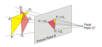
Since the human eye sees three dimensions, the mathematical model represented inside the computer must be transformed back so that the human eye can correlate the image to a realistic one. But the fact that the display device—namely a monitor—can display only two dimensions means that this mathematical model must be transferred to a two-dimensional image. Often this is done using projection; mostly using perspective projection. The basic idea behind the perspective projection, which unsurprisingly is the way the human eye works, is that objects that are further away are smaller in relation to those that are closer to the eye. Thus, to collapse the third dimension onto a screen, a corresponding operation is carried out to remove it—in this case, a division operation.
Orthographic projection is used mainly in CAD or CAM applications where scientific modeling requires precise measurements and preservation of the third dimension.
Reflection and shading models
Modern 3D computer graphics rely heavily on a simplified reflection model, called Phong reflection model (not to be confused with Phong shading).
In refraction of light, an important concept is the refractive index. In most 3D programming implementations, the term for this value is "index of refraction," usually abbreviated "IOR."
Popular reflection rendering techniques in 3D computer graphics include:
- Flat shading: A technique that shades each polygon of an object based on the polygon's "normal" and the position and intensity of a light source.
- Gouraud shading: Invented by H. Gouraud in 1971, a fast and resource-conscious vertex shading technique used to simulate smoothly shaded surfaces.
- Texture mapping: A technique for simulating a large amount of surface detail by mapping images (textures) onto polygons.
- Phong shading: Invented by Bui Tuong Phong, used to simulate specular highlights and smooth shaded surfaces.
- Bump mapping: Invented by Jim Blinn, a normal-perturbation technique used to simulate wrinkled surfaces.
- Cel shading: A technique used to imitate the look of hand-drawn animation.
3D graphics APIs
3D graphics have become so popular, particularly in computer games, that specialized APIs (application programming interfaces) have been created to ease the processes in all stages of computer graphics generation. These APIs have also proved vital to computer graphics hardware manufacturers, as they provide a way for programmers to access the hardware in an abstract way, while still taking advantage of the special hardware of this-or-that graphics card.
These APIs for 3D computer graphics are particularly popular:
- OpenGL and the OpenGL Shading Language
- OpenGL ES 3D API for embedded devices
- Direct3D (a subset of DirectX)
- RenderMan
- RenderWare
- Glide API
- TruDimension LC Glasses and 3D monitor API
There are also higher-level 3D scene-graph APIs that provide additional functionality on top of the lower-level rendering API. Such libraries under active development include:
- QSDK
- Quesa
- Java 3D
- Gsi3d
- JSR 184 (M3G)
- Vega Prime by MultiGen-Paradigm
- NVidia Scene Graph
- OpenSceneGraph
- OpenSG
- OGRE
- JMonkey Engine
- Irrlicht Engine
- Hoops3D
- UGS DirectModel (aka JT)
Applications
- Special effects
- Video games
ReferencesISBN links support NWE through referral fees
- McConnell, Jeffrey J. 2005. Computer Graphics: Theory Into Practice. Sudbury, MA: Jones & Bartlett Pub. ISBN 0763722502.
- Vince, John. 2005. Mathematics for Computer Graphics. New York: Springer. ISBN 1846280346.
- Watt, Alan H. 1999. 3D Computer Graphics, 3rd edition. Boston: Addison Wesley. ISBN 0201398559.
External Links
All links retrieved January 7, 2024.
- CGSociety The Computer Graphics Society.
Credits
New World Encyclopedia writers and editors rewrote and completed the Wikipedia article in accordance with New World Encyclopedia standards. This article abides by terms of the Creative Commons CC-by-sa 3.0 License (CC-by-sa), which may be used and disseminated with proper attribution. Credit is due under the terms of this license that can reference both the New World Encyclopedia contributors and the selfless volunteer contributors of the Wikimedia Foundation. To cite this article click here for a list of acceptable citing formats.The history of earlier contributions by wikipedians is accessible to researchers here:
- Computer_graphics history
- 2D_computer_graphics history
- 3D_computer_graphics history
- Utah_teapot history
The history of this article since it was imported to New World Encyclopedia:
Note: Some restrictions may apply to use of individual images which are separately licensed.
