Switch

A switch is a device that can connect and disconnect an electric circuit. Switches have been built in a wide range of sizes and types, from subminiature devices up to industrial plant switches that regulate megawatts of power on high voltage distribution lines. In applications where multiple switching options are required (such as for a telephone service), mechanical switches have long been replaced by electronic switching devices that can be automated and intelligently controlled.
The switch may also take the form of a "logic gate." Logic gates are most often used in electronic devices with the aid of diodes or transistors, but they can also be constructed using electromagnetic relays, optics, molecules, or mechanical elements. A computer is a system of electronic switches that function as logic gates.
A railroad switch is not electrical, but a mechanical device to divert a train from one track to another.

A simple electrical switch
Contacts

In the simplest case, a switch has two pieces of metal called contacts that touch to make a circuit, and separate to break the circuit. The contact material is chosen for its resistance to corrosion, because most metals form insulating oxides that would prevent the switch from working. Contact materials are also chosen on the basis of electrical conductivity, hardness (resistance to abrasive wear), mechanical strength, low cost and low toxicity.[1]
Sometimes the contacts are plated with noble metals. They may be designed to wipe against each other to clean off any contamination. Nonmetallic conductors, such as conductive plastic, are sometimes used.
Actuator
The moving part that applies the operating force to the contacts is called the actuator, and may be a toggle or dolly, a rocker, a push-button, or any type of mechanical linkage.
Contact arrangements

A pair of contacts is said to be "closed" when there is no space between them, allowing electricity to flow from one to the other. When the contacts are separated by an insulating air gap, an air space, they are said to be "open," and no electricity can flow at typical voltages.
Switches can be and are classified according to the arrangement of their contacts in electronics fields—but electricians in the electrical wiring service business and their electrical supplier industries use different nomenclature, such as "one-way," "two-way," "three-way," and "four-way" switches—which have different meanings in North American and British cultural regions as is delineated in the table below.
Some contacts are normally open (Abbreviated "n.o." or "no") until closed by operation of the switch, while others are normally closed ("n.c." or "nc") and opened by the switch action, where the abbreviations given are commonly used on electronics diagrams for clarity of operation in assembly, analysis, or troubleshooting. The serve to synchronize meaning with possible mistakes in wiring assembly, where wiring part of switch one way and part another (usually opposite) way will pretty much guarantee things won't work as designed.
A switch with both types of contact is called a changeover switch or "make-before-break" switch contact, whereas most switches have a spring-loaded action that momentarily disconnect the load and so are "break-before-make" types. The type of switch used could be important, if for example, the switch selects two different power sources instead of switching circuit loads, or the circuit load will not and cannot tolerate any interruption in applied power.
The terms pole and throw are also used to describe switch contact variations. A pole is a set of contacts, the switch's electrical terminals that are connected to and belong to a single circuit, usually a load. A throw is one of two or more positions (the nomenclature is also applied to rotary switches, which can have many 'throw' positions) that the switch can adopt, which normally, but not always correspond to the number positions the switch handle or rotor can take when connecting between the common lead of the switch and a pole or poles. A throw position which connects no terminals (poles), has a mismatch between positions and positions which connect terminals, but are quite useful to turn things "Off" or for example, alternatively select between two scaled modes of operation. (For example, Bright illumination, moderate illumination, no illumination.)
These terms give rise to abbreviations for the types of switch used in the electronics industry, such as "single-pole, single-throw" (SPST) (the simplest type, "on or off") or "single-pole, double-throw" (SPDT), connecting either of two terminals to the common terminal. In electrical power wiring (that is, House and building wiring by electricians) names generally involving the suffixed word "-way" are used; however, these terms differ between British and American English and the terms two way and three way are used in both with different meanings.
| Electronics specification abbreviation |
Expansion of abbreviation |
British mains wiring name |
American electrical wiring name |
Description | Symbol | IEC 60617 |
|---|---|---|---|---|---|---|
| SPST | Single pole, single throw | One way | Two way | A simple on-off switch: The two terminals are either connected together or not connected to anything. An example is a light switch. | ||
| SPDT | Single pole, double throw | Two way | Three way | A simple changeover switch: C (COM, Common) is connected to L1 or to L2. | ||
| SPCO SPTT, c.o. |
Single pole changeover or Single pole, centre off or Single Pole, Triple Throw |
Similar to SPDT. Some suppliers use SPCO/SPTT for switches with a stable off position in the centre and SPDT for those without. | ||||
| DPST | Double pole, single throw | Double pole | Double pole | Equivalent to two SPST switches controlled by a single mechanism |  |
|
| DPDT | Double pole, double throw | Equivalent to two SPDT switches controlled by a single mechanism: A is connected to B and D to E, or A is connected to C and D to F. |  |
|||
| DPCO | Double pole changeover or Double pole, centre off |
Equivalent to DPDT. Some suppliers use DPCO for switches with a stable off position in the centre and DPDT for those without. | ||||
| Intermediate switch | 4-way switch | DPDT switch internally wired for polarity-reversal applications: only four rather than six wires are brought outside the switch housing; with the above, B is connected to F and C to E; hence A is connected to B and D to C, or A is connected to C and D to B. |  |
Switches with larger numbers of poles or throws can be described by replacing the "S" or "D" with a number or in some cases the letter "T" (for "triple"). In the rest of this article the terms SPST, SPDT, and intermediate will be used to avoid the ambiguity in the use of the word "way."
Make-before-break, break-before-make
In a multi-throw switch, there are two possible transient behaviors in moving from one position to another. In some switch designs, the new contact is made before the old contact is broken. This is known as make-before-break, and ensures that the moving contact never sees an open circuit (also referred to as a shorting switch). The alternative is break-before-make, where the old contact is broken before the new one is made. This ensures that the two fixed contacts are never shorted to each other. Both types of design are in common use, for different applications.
Biased switches
A biased switch is one containing a spring that returns the actuator to a certain position. The "on-off" notation can be modified by placing parentheses around all positions other than the resting position. For example, an (on)-off-(on) switch can be switched on by moving the actuator in either direction away from the centre, but returns to the central off position when the actuator is released.
The momentary push-button switch is a type of biased switch. The most common type is a push-to-make switch, which makes contact when the button is pressed and breaks when the button is released. A push-to-break switch, on the other hand, breaks contact when the button is pressed and makes contact when it is released. An example of a push-to-break switch is a button used to release a door held open by an electromagnet. Changeover push button switches do exist but are even less common.
Special types
Switches can be designed to respond to any type of mechanical stimulus: for example, vibration (the trembler switch), tilt, air pressure, fluid level (the float switch), the turning of a key (key switch), linear or rotary movement (the limit switch or microswitch), or presence of a magnetic field (the reed switch).
Mercury tilt switch
The mercury switch consists of a drop of mercury inside a glass bulb with 2 contacts. The two contacts pass through the glass, and are connected by the mercury when the bulb is tilted to make the mercury roll on to them.
This type of switch performs much better than the ball tilt switch, as the liquid metal connection is unaffected by dirt, debris and oxidation, it wets the contacts ensuring a very low resistance bounce free connection, and movement and vibration do not produce a poor contact.
Knife switch
Knife switches are unique, because rather than employing an enclosed circuit connection area with a rubber- or plastic-insulated section for the user, the contacts and bridge are fully exposed.
The "knife," a flat metal swinging arm, oscillates via user operation between a set of two or more contact areas. The knife and contacts are typically formed of copper, steel, or brass, depending on the application.
The primary advantage of a knife switch is the extremely high current capabilities inherent to the design. The amount of surface area on the "knife" that shorts the contacts is also extremely high, allowing a wide range of high voltage or high amperage applications with no circuit degradation, choke, or arcing during the switch throw. Thicker components need only be accompanied by wider contacts to conduct higher voltages, which allows the design to scale extremely well with size.
Although knife switches are inferior to traditional switches in applications where user safety are paramount, knife switches are still commonly employed in everyday high-voltage applications such as building transformers, large power relays, air-conditioning units, and so on.
Others
A simple semiconductor switch is a transistor. Other types of switch include:
- Centrifugal switch
- DIP switch
- Hall-effect switch
- Inertial switch
- Membrane switch
- Toggle switch
- Transfer switch
- Mindy switch
- Time switch
- Vandal resistant switch
- Jamie switch
Intermediate switch
A DPDT switch has six connections, but since polarity reversal is a very common usage of DPDT switches, some variations of the DPDT switch are internally wired specifically for polarity reversal. These crossover switches only have four terminals rather than six. Two of the terminals are inputs and two are outputs. When connected to a battery or other DC source, the 4-way switch selects from either normal or reversed polarity. Intermediate switches are also an important part of multiway switching systems with more than two switches (see next section).
Multiway switching
Multiway switching is a method of connecting switches in groups so that any switch can be used to connect or disconnect the load. This is most commonly done with lighting.
Two locations

2. Second method
3. Labeling of switch terminals
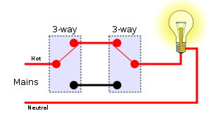
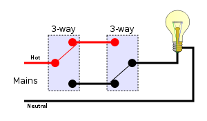
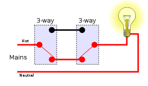
Switching a load on or off from two locations (for instance, turning a light on or off from either end of a flight of stairs) requires two SPDT switches. There are two basic methods of wiring to achieve this, and another not recommended.
In the first method, mains is fed into the common terminal of one of the switches; the switches are then connected through the L1 and L2 terminals (swapping the L1 and L2 terminals will just make the switches work the other way round), and finally a feed to the light is taken from the common of the second switch. A connects to B or C, D connects to B or C; the light is on if A connects to D, that is, if A and D both connect to B or both connect to C.
The second method is to join the three terminals of one switch to the corresponding terminals on the other switch and take the incoming supply and the wire out to the light to the L1 and L2 terminals. Through one switch A connects to B or C, through the other also to B or C; the light is on if B connects to C; that is, if A connects to B with one switch and to C with the other.
Wiring needed in addition to the mains network (not including protective earths):
First method:
- Double wire between both switches
- Single wire from one switch to the mains
- Single wire from the other switch to the load
- Single wire from the load to the mains
Second method:
- Triple wire between both switches
- Single wire from any position between the two switches, to the mains
- Single wire from any position between the two switches, to the load
- Single wire from the load to the mains
If the mains and the load are connected to the system of switches at one of them, then in both methods we need three wires between the two switches. In the first method one of the three wires just has to pass through the switch, which tends to be less convenient than being connected. When multiple wires come to a terminal they can often all be put directly in the terminal. When wires need to be joined without going to a terminal a crimped joint, piece of terminal block, wire nut or similar device must be used and the bulk of this may require use of a deeper back box.
Using the first method, there are four possible combinations of switch positions: Two with the light on and two with the light off. N.B. This diagram uses the American electrical wiring name from the table above.
Off On 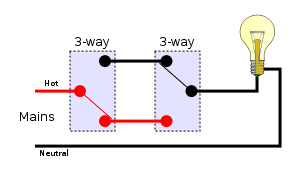


An unrecommended method
If there is a hot (a unique phase) and a neutral wire in both switches and just one wire between them where the light is connected (as in the picture), one can then solve the two way switch problem easily: Just plug the hot in the top from switch, the neutral in the bottom from switch and the wire that goes to the light in the middle from the switch. After doing this in both switches, one would have a fully functional two way switch.
This works like the first method above: There are four possibilities and just in two of them there is a hot and a neutral connected in the poles of the light. In the other ones, both poles are neutral or hot and then no current flows because the potential difference is zero.
The advantage of this method is that it uses just one wire to the light, having a hot and neutral in both switches.
The reason why this is not recommended is that the light socket pins may still be hot even with the light off, which poses a risk when changing a bulb. Another problem with this method is that in both switches there will be hot and neutral wires entering a single switch, which can lead to a short circuit in the event of switch failure, unlike the other methods.
This method is in defiance of the National Electrical Code (U.S.) and the Canadian Electrical Code. In nearly any and all applications, neutral conductors should never be switched. Not only is this a shock hazard due to mistakenly believing that a hot conductor is switched off; it is also a fire hazard and can destroy sensitive equipment due to excessive and unbalanced current flowing on hot conductors that would otherwise flow back to ground on the neutral conductor.
More than two locations

1. First method
2. Second method
3. Labeling of switch terminals
For more than two locations, the two cores connecting the L1 and L2 of the switches must be passed through an intermediate switch (as explained above) wired to swap them over. Any number of intermediate switches can be inserted, allowing for any number of locations.
Wiring needed in addition to the mains network (not including protective earths):
First method:
- Double wire along the sequence of switches
- Single wire from the first switch to mains
- Single wire from the last switch to the load
- Single wire (neutral) from load to mains
Second method:
- Double wire along the sequence of switches
- Single wire from first switch to last switch
- Single wire from anywhere between two of the switches to the mains
- Single wire from anywhere between the same two switches to the load
- Single wire (neutral) from load to mains
Using the first method, there are eight possible combinations of switch positions: Four with the light on and four with the light off. N.B. This diagram also uses the American electrical wiring name from the table above.
Off On 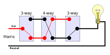
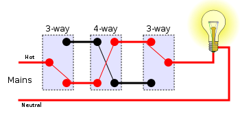
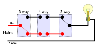
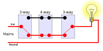
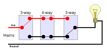
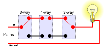
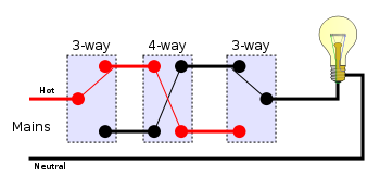
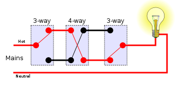


As mentioned above, the above circuit can be extended by using multiple 4-way switches between the 3-way switches to extend switching ability to any number of locations.
Power switching
When a switch is designed to switch significant power, the transitional state of the switch as well as the ability to stand continuous operating currents must be considered. When a switch is on its resistance is near zero and very little power is dropped in the contacts; when a switch is in the off state its resistance is extremely high and even less power is dropped in the contacts. However when the switch is flicked the resistance must pass through a state where briefly a quarter (or worse if the load is not purely resistive) of the load's rated power is dropped in the switch.
For this reason, most power switches (most light switches and almost all larger switches) have spring mechanisms in them to make sure the transition between on and off is as short as possible regardless of the speed at which the user moves the rocker.
Power switches usually come in two types. A momentary on-off switch (such as on a laser pointer) usually takes the form of a button and only closes the circuit when the button is depressed. A regular on-off switch (such as on a flashlight) has a constant on-off feature. Dual-action switches incorporate both of these features.
Inductive loads
When a strongly inductive load such as an electric motor is switched on input surge current which may be several times larger than the steady current flows. When switched off, the current cannot drop instantaneously to zero; a spark will jump across the opening contacts. Switches for inductive loads must be rated to handle these cases. The spark will cause electromagnetic interference if not suppressed; a snubber network of a resistor and capacitor in series will quell the spark. Exact values can be optimized for the particular application, but for many cases a 100 ohm resistor in series with a 100 nanofarad capacitor will do.
Up or down
Domestic light switches are generally moved up to switch on in the US, but down in most of Europe and Australia.
The reason for the difference remains a bit of a mystery. A few hypotheses are often put forward, but none have been validated. Since there is no significant technical reason for either preference, the standards likely developed due to chance and some degree of cultural isolation.
In countries prone to earthquakes, such as Japan, most switches rock sideways to prevent the switch from inadvertently being turned on or off by falling objects.
Contact bounce
Contact bounce (also called chatter) is a common problem with mechanical switches and relays. Switch and relay contacts are usually made of springy metals that are forced into contact by an actuator. When the contacts strike together, their momentum and elasticity act together to cause bounce. The result is a rapidly pulsed electrical current instead of a clean transition from zero to full current. The waveform is then further modified by the parasitic inductances and capacitances in the switch and wiring, resulting in a series of damped sinusoidal oscillations. This effect is usually unnoticeable in AC mains circuits, where the bounce happens too quickly to affect most equipment, but causes problems in some analogue and logic circuits that respond fast enough to misinterpret the on-off pulses as a data stream.[2]
Sequential digital logic circuits are particularly vulnerable to contact bounce. The voltage waveform produced by switch bounce usually violates the amplitude and timing specifications of the logic circuit. The result is that the circuit may fail, due to problems such as metastability, race conditions, runt pulses and glitches.
There are a number of techniques for debouncing (mitigating the effects of switch bounce). They can be split into wet contacts, timing based techniques and Hysteresis based techniques.
Wet contacts
Mercury wetted switch contacts do not suffer from bounce, as once the connection is made the mercury keeps the contact conducting during mechanical bounce.
Mercury wetted switches are not a popular option today, primarily due to mercury's toxicity.
Timing based
Resistor and capacitor

If an on/off switch is used with a pull up (or pull down) resistor and a single capacitor is placed over the switch (or across the resistor, but this can cause nasty spikes of current on the power supply lines) then when the switch is closed (generally pressed) the capacitor will almost instantly discharge through the switch. But when the switch is opened (generally released) the capacitor takes some time to recharge. Therefore contact bounce will have negligible effect on the output. The slow edges can be cleaned up with a Schmitt trigger if necessary. This method has the advantage of fast response to the initial press but the current surges through the switch may be undesirable. Other RC based systems are also possible with various responses and such systems are probably the easiest method when constructing with simple logic gates and discrete components.
State machines and software
A finite state machine or software running on a CPU can be designed to wait a fixed number of clock cycles after any transition before registering another one. This provides a cheap option for debouncing when a microprocessor, microcontroller, or gate array is already in use but is unlikely to be worthwhile if constructing with single logic gates CLPD's.
Hysteresis
Alternatively, it is possible to build in hysteresis by making the position where a press is detected separate from that where a release is detected. As long as the bounces are small enough not to take the switch between these positions, bounce problems will be eliminated. Hysteresis can be mechanical or electronic (for example, a Schmitt trigger).
Changeover switch
A changeover switch provides two distinct events, the making of one contact and the breaking of the other. These can be used to feed the inputs of a flip-flop. This way the press will only be detected when the pressed contact is made and the release will only be detected when the released contact is made. When the switch is bouncing around in the middle no change is detected. To get a single logic signal from such a setup a simple SR latch can be used.
Variable resistance
Normal switches are designed to give a hard on-off but it is also possible to design one that varies more gradually between the hard-on and hard-off states. This keeps the output changes caused by bouncing small. Then by feeding the output to a Schmitt trigger the effect of those bounce based changes can be eliminated.
See also
- Circuit breaker
- Electricity
Notes
- ↑ Tanaka Precious Metals, General Electric Contact Materials.
- ↑ P.M.B. Walker, Chambers Science and Technology Dictionary (Edinburgh, UK: Cambridge University Press, 1988, ISBN 1852961503).
ReferencesISBN links support NWE through referral fees
- Dorf, Richard C., and James A. Svoboda. 2006. Introduction to Electric Circuits. Hoboken, NJ: J. Wiley & Sons. ISBN 0471730424.
- Walker, PMB. 1988. Chambers Science and Technology Dictionary. Edinburgh, UK: Cambridge University Press. ISBN 1852961503.
- Yan, Ping. 2008. Fluorescent Switches, Sensors, and Nanostructures. New York, NY: Thesis (Ph. D.), Columbia University. ISBN 3836481154.
External links
All links retrieved February 26, 2023.
- Several Wiring Options (with diagrams).
- Residential wiring diagrams.
Credits
New World Encyclopedia writers and editors rewrote and completed the Wikipedia article in accordance with New World Encyclopedia standards. This article abides by terms of the Creative Commons CC-by-sa 3.0 License (CC-by-sa), which may be used and disseminated with proper attribution. Credit is due under the terms of this license that can reference both the New World Encyclopedia contributors and the selfless volunteer contributors of the Wikimedia Foundation. To cite this article click here for a list of acceptable citing formats.The history of earlier contributions by wikipedians is accessible to researchers here:
The history of this article since it was imported to New World Encyclopedia:
Note: Some restrictions may apply to use of individual images which are separately licensed.